Quantcast
Channel: Evothings | RSS Feed
Viewing all 97 articles
Browse latest View live

Shellshock – exactly what is the impact to IoT?

$
0
0

Over the past few days a lot of focus has been placed on what is known as the ShellShock exploit that impacts all computers and devices that use the Bourne-Again Shell (bash). Exactly how serious is this bug, what are the implications specifically related to the Internet of Things and why should consumers care about this?

If you are using Mac OSX, Windows, Linux (or *NIX variant) or even a mobile device that has the Unix shell ‘bash’ in its core – you may be using a system that is vulnerable to attack. It extends beyond personal computing as well; 67.4% of all web servers (source: Feb, 2014) use a *NIX based operating system that have bash installed.

So exactly what is the ShellShock exploit? Symantec explain it in simple terms:

This isn’t the first time we’ve seen panic come out of a computer bug – just recently there was a lot of hype about the Open SSL bug known as Heartbleed (original advisory). But we have also seen bugs that have existed for 20+ years before finally getting identified and fixed – such as the BSD *dir() library (25 years), Yacc bug (33 years) and one that even was sent to Mars with the Curiosity Rover – the Lempel-Ziv-Oberhumer (LZO) compression (20 years).

A lot of discussion – and a very simple example has been posted on websites such as security.stackexchange.com and wikipedia.org outline a series of simple examples that could be used to obtain secret files or even remove or replace important files. Just by setting the User-Agent: attribute while browsing a CGI script – evil can be done; one user on twitter posted an example that would conceptually update (unverified) bash and reboot a server.

Running a simple test on my own Macbook Pro (in Terminal window):

$ env val='() { :; }; echo "bad command"' bash -c "echo good command"
bad command
good command

The bad command is sneakily stored within the string being assigned to val – but gets executed. The solution is to either download and compile a new version of bash from source (too difficult for most people) or wait for an official update from the operating system provider.

Unfortunately, as IoT devices get more processing power and memory it is common to install a *NIX variant on them which would also make those devices exploitable by the same attack. The Arduino Yún, Intel Galileo, Raspberry Pi, BeagleBone or any other IoT device that uses a *NIX variant as its base operating system can be affected.

In regards to security and IoT – this is a massive vulnerability and concern.

Exploits do not always happen due to badly written software – the majority of them, like many identified in the recent report by Hewlett Packard stating 70% of IoT devices are insecure, are due to flaws in the underlying operating system (openSSL, bash et al).

Even with detailed understanding of the bug there may be even more vulnerabilities due to the basic design of how bash was designed and the manner in which the parser and command execution handler was implemented (being too clever for its own good).

One of the things that I particularly like about the Arduino platform and by having such limited processing power is that the devices run in what is known as “bare bones” mode – meaning that the only program on the device is the software itself resulting in less points of attack.

As computational power increases on IoT devices, the move should be to focus on bare bones programming – not piggy backing on *NIX based operating systems that are more likely to be vulnerable to 0-day attacks that are found even on desktop and server platforms that can be also applied onto IoT based devices.

Imagine the devices already on the market with this exploit – with no mechanism to update.


A quick walk through the Evothings Arduino BLE example

$
0
0

redbearlabs-blend-arduinobleAt Evothings we take pleasure in showing how simple it is to interact with IoT devices from an iOS or Android mobile device.

At the numerous conferences and events we have attended over the past few months – one of our examples tends to be quite popular, as it grabs the attention of the audience we are demonstrating for, is our Arduino BLE example.

Mikael Kindborg, one of our team members, recently wrote up an in-depth and detailed getting started with BLE guide which you should definitely read over to understand the basics of Bluetooth Low Energy.

Not only is the example interactive on the both the Arduino and mobile device simultaneously, but it is also demonstrates two-way communication between the devices using Bluetooth Low Energy communications protocol.

From a hardware perspective there is a small “shopping list” that is required we used the following components:

Any Arduino compatible micro-controller can be used, if you already have one – you could also use the BLE Shield or any shield that uses the Nordic Semiconductor nRF8001 chipset. Our example was built based on this chipset – however it could be quite easily modified to support additional chipsets and their associated SDKs.

arduinoble-components

Part of the fun is actually wiring up the circuitry, we often run workshops where attendees can do this on their own or with our assistance. Inside the example documentation is a fritzing diagram that outlines how to connect the various components to each other and the Arduino.

To make things easier to understand it is recommended to use a red wire for 5V and black wire for GND (ground) as some components actually do have to be orientated the right way to function – such as the LED. A 220 Ohm resistor is used to reduce the voltage from 5V to something the LED can handle – depending on the voltage rating of the LED it may vary; but in this example using a 220 Ohm gives a nice bright glow.

Arduino Sketch

The Arduino Sketch is located in the examples/arduino-ble/arduinoble directory.

On startup the setup() function is called and a number of underlying system and BLE functions are called to configure digital PIN 2 in output mode, analog PIN A0 in input mode and start the underlying BLE communications system with the identifying name of “arduinoble” so it can be identified from the mobile application.

In the loop() function, the following code is available:

void loop() 
{
	// If there's any input...
	while(ble_available()) {
		// Read input.
		int c = ble_read();
		if(c != 0) {
			// Non-zero input means "turn on LED".
			Serial.write(c);
			digitalWrite(LED_PIN, HIGH);
		} else {
			// Input value zero means "turn off LED".
			Serial.write('0');
			digitalWrite(LED_PIN, LOW);
		}
	}

	// Read the analog input pin and send the data over BLE.
	short i = analogRead(INPUT_PIN);
	ble_write_bytes((byte*)&i, 2);

	// Process BLE events.
	ble_do_events();
}

In this code a single byte that has been sent from the mobile device is read from the BLE communications channel and depending on its value – the LED is either turned on or off using the digitalWrite function. Once complete a call to analogRead is performed to read the value from the potentiometer and the resulting value which is between 0 and 1023 (by default, the analog input has 10-bit precision) is written to the BLE communications channel which will be received on the mobile device.

Simply ensure you have the appropriate libraries for the Nordic nRF8001 chipset (you can also use the RedBearLabs libraries available in their getting-started guide) and upload the sketch to your Arduino device using the Arduino IDE.

Evothings App

There are two main components in the Evothings App – the first is the scanning and connection from the mobile device to the BLE chipset on the Arduino, if you look at the following code it is quite simple to see that setting the BLE name was important to identify which device we should connect to.

    evothings.ble.startScan(
      function(deviceInfo)
      {
        if (app.knownDevices[deviceInfo.address])
        {
          return;
        }
        console.log('found device: ' + deviceInfo.name);
        app.knownDevices[deviceInfo.address] = deviceInfo;
        if (deviceInfo.name == 'arduinoble' && !app.connectee)
        {
          console.log('Found arduinoble');
          connectee = deviceInfo;
          app.connect(deviceInfo.address);
        }
      },

In the user interface there are two HTML buttons that have their onClick states defined to call the app.on() and app.off() functions – which writes a single byte to the BLE characteristic providing serial communication; namely 1 for on and 0 for off.

  on: function()
  {
    app.write(
      'writeCharacteristic',
      app.deviceHandle,
      app.characteristicWrite,
      new Uint8Array([1])); // 1 = on
  },

  off: function()
  {
    app.write(
      'writeCharacteristic',
      app.deviceHandle,
      app.characteristicWrite,
      new Uint8Array([0])); // 0 = off
  },

For receiving information from the Arduino, the application configures a notification handler to process information as it is received from the BLE communications channel by converting two bytes into a 16-bit integer to obtain the values between 0 and 1023 that was originally sent from the Arduino.

    // Start reading notifications.
    evothings.ble.enableNotification(
      deviceHandle,
      app.characteristicRead,
      function(data)
      {
        app.drawLines([new DataView(data).getUint16(0, true)]);
      },
      function(errorCode)
      {
        console.log('enableNotification error: ' + errorCode);
      });

With a bit of JavaScript and Canvas 2D code a buffer of data points (as they are collected) are plotted to the mobile display in real time. As the user rotates the potentiometer the graph updates to reflect the current analog value obtained from the Arduino.

Conclusion

Once you manage to connect everything together and start the application on the mobile device – you should have something like the following you can interact with:

redbearlabs-blend-arduinoble

Now that we have outlined how the application works under the hood – why don’t you grab a copy of Evothings Studio and try it out for yourself! If you create some cool and interesting projects or have questions on how to get started, you can post information and questions to our forum.

Getting started with Evothings Studio in 90 seconds

$
0
0

This guide shows how to get started with developing mobile applications for the Internet of Things using Evothings Studio. Use your web development skills to code mobile apps in JavaScript and HTML that now have access to socket networking, BLE and iBeacon APIs.

Get started within minutes

It is easy to get started with mobile IoT application development using Evothings Studio. Here is what you need:

  • Some basic knowledge about JavaScript and HTML.
  • The Evothings Studio Workbench desktop application (get it with the Evothings Studio download).
  • The Evothings Client mobile application (get it from Apple App Store or Google Play).
  • A text editor (pick your favourite editor!)
  • A WiFi network that allows connections between your phone and your computer.

With the above setup, you have everything you need to get going with mobile app development for the Internet of Things, including APIs for sockets, BLE (Bluetooth Low Energy) and iBeacon. Furthermore, you get a very nice live reload functionality that boosts development time by a factor 5 or more (i.e the edit/build/test cycle takes seconds rather than up to a minute as with Android Studio or Xcode).

Watch the above video for an introduction that shows how to run and edit the “Hello World” example app in Evothings Studio.

First time step-by-step guide

Here is a step-by-step guide to get you going, right from scratch:

  • Download Evothings Studio to your computer (the download contains Evothings Workbench, examples and documentation).
  • Install the Evothings Client app on your mobile device(s).
  • Make sure both your computer and mobile device are on the same WiFi network and that the network allows machines to reach each other.
  • Start Evothings Workbench.
  • Launch Evothings Client.
  • On the phone; connect to the Workbench from the app.
  • On your computer; press the RUN button on the “Hello World” example in the Workbench.
  • Done! You have now run your first app using Evothings Studio.

How to edit code

Next step is to modify the example code:

  • Press the CODE button on the “Hello World” example.
  • Open the index.html file in a text editor.
  • Make some interesting changes to the code – e.g. modify the heading to say “Hello Evothings”. ;-)
  • Save changes in the editor.
  • Done! The app now automatically reloads on the device – changes are instantly visible.

Create your own project

To create your own mobile application project, follow these steps:

  • Create a folder with the project files (HTML/CSS/JavaScript/media files).
  • There needs to be at least one HTML file in the project – used as the entry point of the app.
  • Drag the main HTML file, e.g. the index.html,  into the project list in Evothings Workbench.
  • Now just press RUN on the project to launch it on the connected device.
  • Note that you can connect multiple mobile phones and tablets to Evothings Workbench. When you save any file in the project (or press RUN again), the app will reload on all of them!

An Evothings app project is just a folder with your HTML and JavaScript files. Just like any web site. And as soon as anything is changed, the Workbench pushes it to all connected clients, just like that!

How to publish an app

There are two ways to publish a mobile application developed with Evothings Studio:

  • Upload the project files to a web server and use Evothings Client to run the app. Just enter the URL to the main HTML file on the web server in Evothings Client and tap CONNECT. Read more here.
  • Build a native app using Cordova. Check out the documentation for building native apps to learn more.

Useful hints

  • Press the “Tools” button in the Workbench to use debug logging and JavaScript evaluation tools.
  • Read more about the Workbench in the documentation.
  • Get inspired by the tutorial blogposts. Many of them contain fully working examples you can use.

Get started right away

Download Evothings Studio now and get started within minutes. It is fun and easy!

How to make an app for remote controlling an elevator (part 1)

$
0
0
App for calling and unlocking the doors of an elevator.

App for calling and unlocking the doors of an elevator.

During a previous developers’ Hack Night, we decided to connect the office elevator to the internet and a mobile app. With the use of an Electric Imp, together with a simple electronic circuit and a simple mobile application developed with Evothings Studio in html and javascript, we could remotely both call the elevator and unlock its doors from anywhere.

Our previous office’s elevator had locked doors at each floor, and when a visitor arrived at our floor they had to ring a bell to let us know they wanted to be let inside. We had to really run down a long corridor to press a button that unlocked the doors, to not let the elevator depart to another floor with our visitor inside it. With a remote control in our pocket we could comfortably unlock the doors from anywhere.

Electric Imp introduction

Electric Imp with electronics for elevator control.

Electric Imp with electronics for elevator control.

The Electric Imp was an obvious choice of hardware for solving our problem because it could easily fit inside the elevator control panel and it was easy to set up. It is a computer having the size of an SD-card, that contains a Cortex M3 processor and a WiFi module.

Software development is made through the online Electric Imp IDE and hardware development is made easy with a breakout board. The modules and breakout boards can be purchased for example from SparkFun Electronics or DigiKey.

There are six software-configurable I/O ports on the Electric Imp. Each pin can be configured during run-time to one of several specialized functions. These functions includes UART, I2C, SPI, analog in and out, PWM and GPIO. The built-in WiFi module supports WPA2 encryption and the data passed between the user and the device goes through a TLS encrypted interface.

Connecting the Electric Imp to the Internet

The first step of getting started developing for the Electric Imp is to connect it to the internet. This is done by performing the following simple steps. Alternatively see Electric Imp’s Getting Started Guide.

  1. Download the Electric Imp app to a mobile device from the App Store or Google Play.
  2. Use the app to log in to your Electric Imp developer’s account.
  3. Specify your WiFi network name and its password.
  4. Connect the Electric Imp to a breakout board and power source.
  5. Transfer your WiFi settings to the Electric Imp by pressing a button in the app and then holding the mobile device’s screen close to the edge of the Electric Imp. The app will make the screen blink rapidly with a pattern containing your WiFi settings, which is detected by a photosensor in the Electric Imp.
  6. Make sure that your Electric Imp is blinking green, which means that the transfer of WiFi settings went through and the connection to the Electric Imp servers is OK. Otherwise try performing the BlinkUp procedure in a darker place to decrease disturbances from other light sources. Refer to the BlinkUp Troubleshooting Guide for more information.
  7. Log in to the Electric Imp IDE on a desktop computer, create a new “model” (application) and assign it to your Electric Imp device. Now you’re ready to start coding! See Part 2 of this article for more information on how to put code on the device.

Wiring up the Electric Imp to the elevator’s control panel

Electric_Imp_elevator_hack_overview

Electric Imp with additional electronics for elevator control.

We needed to give the Electric Imp the ability to activate the elevator control panel’s buttons. For investigating how the control panel worked we carefully removed its cover plate and looked at how the buttons were wired.

With the help of a multimeter we determined that the buttons were connected to 10V and worked much like normal light switches. We decided to connect simple relays between the buttons and the Electric Imp, with some few components in between. A relay is an electrically operated switch, allowing one circuit to close or open a secondary one.

The relays we used required a voltage of 5V but the Electric Imp’s I/O ports give a maximum of 3.6V (see its datasheet for details), and therefore we needed some extra components in between. We used a TS7805 voltage regulator to be able to connect the elevator’s 10V power supply to the relays. A rectifying diode (1N4007) in parallel with each relay protected the circuit from any reverse voltage spikes created by the relays.

The connections, numbered 1 and 2 to the left in the schematics below, was each connected to the Electric Imp’s I/O pins. Each of these were connected to the relays with a transistor. The transistors (two of them, identified as BC547) enabled the very low current flowing from the Electric Imp’s I/O pins to easily control the relays. The connections labeled Switch 1 and Switch 2 were connected to the buttons for calling the elevator and unlocking its doors.

Circuit diagram for Remote Controlled Elevator

Electronic circuit for giving power to the Electric Imp and for activating the elevator’s buttons.

Because we wanted the elevator’s control panel to still look nice and pretty after our hack, we made sure that the Electric Imp could be powered from the control panel’s 10V power source. The April Development Board that we used permits any voltage between 3 and 17V to be used, so we simply could connect the wires between the elevator’s control panel and the development board.

There are some additional components seen in the schematic. The resistor R1 of 10Ω is only for protecting the circuit from any sudden spikes from the elevator’s power supply. The capacitors C1 and C2 make extra sure that the voltage in the circuit keeps at a stable 5V. Resistors R3 and R4 reduce the current drained from the Electric Imp’s I/O ports for decreasing power consumption. Resistor R2 is making sure LED gets the correct voltage. The LED is just for show, letting us know the circuit has power by shining brightly blue.

The next step: write the code for the Electric Imp and mobile application.

In the second post on this hack will tell you how we wrote the simple code that enabled us to take control of the elevator, using Evothings Studio and the Electric Imp IDE. Stay tuned to see this last part of the story about how we hacked our office elevator while eating pizza and drinking beers!

In the meantime, Download Evothings Studio now and get started within minutes. It is fun and easy!

Weekly RIoT 41- our Reflections on the Internet of Things

$
0
0

week# 41, 2o14, Stardate 92377
Screen Shot 2014-10-10 at 3.02.40 PM

Hola!
It’s been very exciting weeks for the entire IoT industry vigorously rolling eyes, as the ShellShock 0-day vulnerability hits a lionpart of devices carrying a bash *NIX shell somewhere deep inside. The AllSeen Alliance have taken a step forward announcing an effort to standardise lighting control and home automation, and ARM have stepped up to the plate with a bare bones approach to making competent embedded systems sans Linux.

Recently, our CTO Aaron took a good look at it and summarized his findings on the threat posed by the Shellshock vulnerability in a post a while ago:
http://evothings.com/shellshock-exactly-what-is-the-impact-to-iot/

The AllSeen Alliance is determined to take a serious look at home automation and lighting control, thereby giving players pushing more proprietary systems like Philips and Osram a run for their money.
http://news.techworld.com/applications/3575709/allseen-alliances-iot-crusade-takes-aim-at-smart-lighting/

Another player joining in by announcing an IoT ecosystem, this time ARM with the mbed OS. Building from scratch with the components you really need, is especially topical these days when ready-made OS alternatives are contain unknowns prone to introduce vulnerabilities.
http://www.ardiri.com/blog/arm_announces_mbed_os_roadmap_for_iot_ecosystem

In preparation for his upcoming house erection project, our CTO Aaron is looking at security cam solutions using standard components, here a fine blogpost using the Yun along with a PIR motion sensor to take mounds of pictures as soon as there’s some action on the scene: https://learn.adafruit.com/wireless-security-camera-arduino-yun/

Getting started with mobile IoT development is very fast at Evothings, here’s your 90 second Hello World tutorial story, as told by our Lead Architect Mikael Kindborg. We hope you’ll like the simplicty and the ultra-short make-ready time, making proper apps by editing web pages.
http://evothings.com/getting-started-with-evothings-studio-in-90-seconds/

Last but least, some IoT for human conditioning. With this Pavlak tracker (and jolting whacker) bracelet for people who just can’t take a hint:
https://www.indiegogo.com/projects/pavlok-the-habit-changing-device-that-shocks-you

That’s all we had for now, have a great week-end and if you have something IoTish to share with the rest of us, don’t be shy to share as we love a good story!

And don’t miss out, subscribe to Evothings monthly sendout via your inbox for a conveinient way of keeping up with the goings on in the world of connected things: http://evothings.com/signup-newsletter/

Live long and prosper
The Evo team

How to make an app for remote controlling an elevator (part 2)

$
0
0
App for calling and unlocking the doors of an elevator.

App for calling and unlocking the doors of an elevator.

Previously we told the story of how we hacked an elevator and talked mostly about the hardware involved. Now we will tell you about the easy part: how to make a mobile app in HTML5 and JavaScript that allowed us to both call and unlock the doors of our office elevator. Using Evothings Studio and the Electric Imp IDE we could quickly develop a working IoT app!

Three simple parts are needed to make the app work: the code for the mobile app itself, the code for the Electric Imp Agent and the code for the Electric Imp Device. We will start by explaining these Agents and Devices and thereafter show the code!

How to communicate with the Electric Imp using Agents and Devices

The Electric Imp is very easy to communicate with. After setting it up like described in Part 1 of this article, it already has an Internet URL accessible from anywhere. This URL looks something like “https://agent.electricimp.com/gpTxbKL5BAq1″ and can be found in the Electric Imp IDE. When you navigate to that URL from a web browser, you are communicating with a service called an Electric Imp Agent that is basically a web server (cloud service) that you are in control of. The Agent service is programmed through the Electric Imp IDE.

We cannot over the Internet communicate directly with the Electric Imp, only through the Electric Imp Agent service. But we can easily forward any information sent to the Agent to the Electric Imp itself, and vice versa. This approach is for many purposes very effective as it for example leads to fewer messages being processed and communicated by the Electric Imp itself, which leads to decreased energy consumption.

Communication-pathway

How our app communicates with the Electric Imp.

Because we have different code running in the cloud, i.e. the Electric Imp Agent, and on the device itself, the term Electric Imp Device is used for the latter to distinguish between these. Multiple Devices can communicate with the same Agent.

Electric Imp Agent and Devices

Example of how a mobile app could communicate with multiple Devices through an Agent.

The Electric Imp is intended to provide Internet connectivity to battery-powered devices like for example scales or motion detectors and for these purposes it doesn’t need a constant internet connection. For more advanced devices, decision-making based on information attained through the Internet can be done in the Agent service, and only if deemed necessary it will be pushed to all connected Devices. The Electric Imp API makes it very simple to write code that sends messages back and forth between the Agent and its connected Devices.

Sending commands to the Electric Imp Agent from the mobile app

Electric_Imp_elevator_remote_app_screenshotOur mobile app needs to simply be composed of two buttons, one for unlocking the elevator’s doors and another for calling the elevator. When pressing one of these buttons, we want a message to be sent to the Electric Imp that turns on one of it’s I/O ports. Because we connected the I/O ports to the elevator’s control panel, the app can then be used to remotely press the control panel’s buttons.

We based the app on the Hello World example bundled with Evothings Studio, by simply making a copy of it, dragging its modifying the text and inserting two buttons and some JavaScript. Testing the app on any device is easy with Evothings Studio as we basically only have to drag the index.html file into the Evothings Workbench project list and press the Run button.

Each button should simply send an HTTP request to the Electric Imp Agent URL when pressed. The URL contains an additional parameter telling the Agent whether we want to unlock the door or call the elevator.  With the help of jQuery, we can make this request with one line of JavaScript, like the following:

$.get('https://agent.electricimp.com/gpTxbKL5BAq1?command=unlock')

Each button is simply composed of an HTML-element with an additional attribute specifying what should happen when we press it, like the following:

<button onclick="unlock_door()">
	Unlock the door
</button>

<button onclick="call_elevator()">
	Call the elevator
</button>

The “unlock_door” and “call_elevator” functions should make the respective HTTP request to the Electric Imp Agent like described above. In the final version of the app’s code we made the JavaScript code even more compact, but for the sake of the article it’s here slightly more verbose.

Receiving messages on the Electric Imp Agent

In the Electric Imp IDE there are two code panes, one for the code running on the Agent and one for the Device. The code we need to write in each of these is very basic, and will be explained in this and the following section. The language used in coding for the Electric Imp is called Squirrel and uses a C-like syntax. The Electric Imp API contains functions for handling HTTP requests, controlling I/O ports, power management, and much more.

Electric Imp IDE and the mobile app controlled elevator.

Electric Imp IDE

Firstly we enable listening for HTTP requests by calling the http.onrequest function in the Agent and giving it a reference to a function that will receive our requests. In this receiving function we check for the “unlock” or “call” commands specified through the Agent URL query string, like the following:

function on_http_request(request, response)
{
    if (request.query.command == "unlock")
    {
        device.send("command", "unlock");
    }
    else if (request.query.command == "call")
    {
        device.send("command", "call");
    }
}

http.onrequest(on_http_request);

Now when we make a request through the URL “https://agent.electricimp.com/gpTxbKL5BAq1?command=unlock”, the Agent will send an “unlock” command to the Electric Imp.

Receiving messages on the Electric Imp Device

In the Electric Imp Device code we simply need to call the agent.on function, specifying that when a message with the title “command” arrives from the Agent, its contents should be sent to a function that we created. This receiving function on the Electric Imp should turn on and off its corresponding I/O port, to activate one of the relays connected to the elevator control panel’s buttons, like following:

function on_command(command)
{
    if (command == "unlock")
    {
        // Press the unlock button (activate relay connected to I/O port 1).
        hardware.pin1.write(1);
 
        // Keep it held for a short moment...
        imp.sleep(0.1);
 
        // Release the unlock button (deactivate relay).
        hardware.pin1.write(0);
    }
}

agent.on("command", on_command);

With this added functionality, when our app makes a request to the URL “https://agent.electricimp.com/gpTxbKL5BAq1?command=unlock”, I/O pin number 1 on our Electric Imp will be turned on. As this pin is connected to the elevator’s control panel, we will have remotely activated one of its buttons by pressing a button in our app!

Full source code

The source code for the mobile app and the Electric Imp can be found in the evothings-gallery repository. Feel free to use it for your own projects!

Go and have fun!

It’s great fun bringing some friends together for a few hours and creating things like this. We hope that you feel inclined to try, and know that even the simplest project gives a great amount of satisfaction!

Download Evothings Studio now and get started within minutes. It is fun and easy!

Blink a LED on the Intel Edison dev board using your smartphone

$
0
0

Intel EdisonHow many javascript developers does it take to blink a LED on the brand new Intel Edison chip? Well, actually not that many once you know how it’s done! The Edison was introduced in its second incarnation in September of 2014 and has a Intel Atom “Tangier” processor at 500MHz, with 1 GB of RAM and 4 GB of flash storage. We’re not going to need much of that goodness to do our blink, while it means that there is potential for expansion.

The good news is that there is a brand new version of the Arduino SDK for Edison and your old sketches – and most of your shields from your Uno – will also work on the Edison platform out of the box. Yes, there are a few hoops you need to negotiate before we get there, in preparing the Edison for take-off, but no programmers were harmed in any way during unboxing or setup.

Preparations

First of all you need to get the latest firmware on-board by following this fairly pedagogical instruction on the Intel developers web site. The mounted partition is empty, and as you’ll see needs to be formatted with a single FAT-32 partition (typically with Disk Utility or similar).

DSC_0123
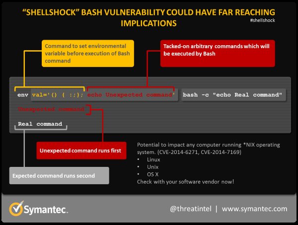
Note: you need two USB – microUSB cables in order to succeed, one for flashing and one for USB power, the standard A-type USB connector (see pic) cannot be successfully exploited for this purpose.

Upon completion, you need to get the designated Arduino software. Note that much of it is common any previous Arduino installations already on your computer, and if that’s the case you might want to rename the application as well as to change the home catalogue for your sketches, not to get them too mixed up under “Arduino>Preferences” in the Arduino SDK:

To get the device name, and WiFi setting right from a Mac, you need to use the Terminal and type at the prompt “screen /dev/cu.usbserial-XYZ 115200 -L“. The XYZ would typically be something else, look in “ls /dev/cu*” for clues. Once connected, hit RETURN a few times to get the the teletype-style connection going, and sign in as “root” (no password for now), and then type “configure_edison –setup”. Follow the instructions and your done.

DSC_0131

That’s it for preparations, now you’re good to go. Try the Examples>01.Basics>Blink to get the on-board green LED (surface mounted on the Edison) to loop blinking steadily on and off.  You’ll quickly recognise the Arduino-style pins, and where you get 5V, GND and the digital pins.

Running Arduino TCP on/off

Evothings WorkbenchBlinking a led on digital pin 2, has become the veritable “Hello, World!” of Evothings studio, and here’s how it’s done, step by step. First open Evothings Studio on your computer, and check that it’s on the same wifi network as your phone. Launch Evothings Client on your phone and press connect on-screen. Some networks don’t allow discovery, so you’ll have to enter the Connect URL address found on the bottom of the Workbench window on the computer. Now, open Evothings Studio, click “CODE” in the Workbench at the Arduino TCP on/off example, and go up one folder in the hierarchy to grab the corresponding Arduino Wifi sketch. Each example has an app folder, and when applicable one or more hardware-centric folders, for drivers, sketches et cetera.

In the sketch code source; configure your WiFi with its SSID/password, press Upload and count to three before opening the Serial Monitor (CONTROL-M or CMD-M) in the Arduino SDK to make sure that you’re given an IP-address from the router.

Finally press RUN in Evothings Studio Workbench in the Arduino TCP on/off example, and connect from your mobile device using the IP address you got from the Serial Monitor, and press CONNECT. Mount a LED light in series (with a 220 Ohm resistor to prevent overheating) between pin 2 and GND, and blink away! Now you can build your own projects, and incorporate mobile services and apps into any of your existing projects and make them better and more fun.

If you haven’t already, you can download Evothings Studio here while the client applications for iOS and Android can be found on major app stores.

IoT Security – are we going about it the right way?

$
0
0

This one is for the way-out-there department but makes for interesting discussion on security, accessibility of data and a biological approach to how IoT systems can begin to defend themselves as nature has proven so effective.

EET India published an article recently that makes a good point of questioning if security within IoT, mobile and computing in general is being actually being tackled appropriately – instead of implementing physical security measures, is there a possibility to learn from biology to protect and adapt against attacks to strengthen each node in a deployment?

Security techniques in the Internet have largely drawn inspiration from physical security—keys, firewalls, trusted zones, and more. However, there are other possible sources of inspiration, biology being an obvious example.

source: quote from EET India article

While technology and biology are two completely different areas – after reading the article and thinking about it closer, there are a lot of interesting points raised that if implemented correctly, could see a rise in adaptable security and diversity in technology; as nature models perfectly.

As HP has reported previously up to 70% of IoT devices are vulnerable, the main reason for this is the lack of diversity and common 0-day attacks being exploited across multiple devices, including the likes of shellshock, heartbleed and blatant lack of security in the first place.

The article also covers the concept of immunological defence that can be adapted for use within technology – that threats are identified based on behavioral factors rather than a database of known signatures that are effectively out of date the second the product ships.

Once an alarm has been triggered the system must respond to the threat – taking the immune style approach; the node could resolve the threat and take one for the team yet at the same time alert neighbouring nodes of the threat to assist isolation of the threat and spawn a redundant node to replace the functions performed by the infected one.

The basic gist is to start out expected to be attacked and focus on protecting the health of the total system understanding a small sacrifice (with learning and fall back concepts) may be the best for the greater good overall – the concept is food for thought for sure.


Watchdog Timers – how to reduce power usage in your Arduino projects

$
0
0

Do you have an Arduino project configured to periodically gather some sensory information and you are noticing it draining power quickly while waiting for the next interval? Do you want to get the maximum operating period on those small batteries?

Then it is time to consider implementing a WatchDog Timer (WDT) so conserve power when your device can power down while not in use.

So, what is a watchdog timer?

A watchdog timer (WDT); sometimes called a computer operating properly or COP timer, or simply a watchdog – is an electronic timer that is used to detect and recover from computer malfunctions.

source: en.wikipedia.org/wiki/Watchdog_timer

While typically used to detect when a computer system crashes or becomes unresponsive – it can also be used to wake up a device if it has been on purpose put into a power down state; something that becomes applicable to saving power and reducing power consumption.

You could theoretically write your own; using the in-built features of the Atmel AVR platform – specifically the <avr/wdt.h>, <avr/sleep.h>, <avr/power.h> and <avr/interrupt.h> headers or you could use a third-party library and save yourself a few headaches trying to perfect an implementation on your own.

Library Repo Links License
Low-Power Project Home, Blog CC-SA 3.0
JeeLib Project Home, Wiki MIT
narcoleptic Project Home GNU GPL v3.0
Enerlib Project Home undefined

I found the above four libraries; some in better states than others and depending on the type of open-source license you are looking for the one you decide on will vary. I took a look at the code state of each project and I believe the “Low-Power” library is streamlined well and very simple to integrate into an existing Arduino project.

The Low-Power library provides three example cases; either to put the device in idle mode for a short timeframe or do a full power down and wake-up after a period of time or after an external interrupt occurs (ie: Serial, sensor or a network event).

#include "LowPower.h"

void setup()
{
  // No setup is required for this library
}

void loop()
{
  // Enter power down state for 8 s with ADC and BOD module disabled
  LowPower.powerDown(SLEEP_8S, ADC_OFF, BOD_OFF);

  // Do something here
  // Example: Read sensor, data logging, data transmission.
}

The above example puts to device to sleep for eight seconds (the maximum interval provided by the AVR hardware) – you could make multiple requests to extend this (2×8 = 16 seconds) or if you want you could hook up an external timer and trigger the wake-up with an interrupt. It also increases the basic compiled sketch size from 450 to 642 bytes (using 1.5.x IDE) and adds a single byte of dynamic memory for the LowPower reference object – minimal for the job.

But while it sounds great – there is a small caveat; power reduction relies not only on software but it also relies on the hardware used and unfortunately a lot of off the shelf devices are not very power efficient due to extra electrical components.

I found a great blog post comparing the power consumption of an Arduino UNO by default with a watchdog timer (45.6mA vs 34.4mA – a small reduction) and using a custom board removing any power hungry components such as regulators and LEDs; to get right down to µA levels. Rocket Scream have a blog post outlining similar results.

The use of watchdog timers in your project could make a drastic difference to the amount of information your Arduino projects could gather and transmit to the cloud; this information could then be displayed on a mobile device by writing an application in Evothings Studio. You’ll find plenty of templates to use in your own projects at the Evothings Studio website for controlling and monitoring your Arduino projects.

Connecting your phone to the LightBlue Bean

$
0
0

Got a LightBlue Bean microprocessor? Great, then this article is for you and others might find it interesting as well. It’s about how to connect your smartphone to the LightBlue Bean, a small form-factor Arduino-clone from PunchThrough Design. We use Bluetooth Low Energy (BLE) and our house toolset Evothings Studio to make this happen. We’ve also shared an example application for you, to use as a starting point for your own projects, showing you how to read and write data utilizing the provided scratch data areas on the LightBlue Bean with an Android or iOS device.

bean_small

Ingredients

To run this example you need the following:

Hardware

  • A LightBlue Bean unit
  • An Apple computer running OS X 10.9 or above
    (Windows Bean loader coming soon)
  • A modern smartphone running BLE hardware

Software

Running under Android requires OS ver 4.3 or later with support for Bluetooth Low Energy communications. Please note that BLE support on Android is still not fully mature, and results may vary and depending the make and model of your device – you may experience difficulties running this example. If the app stops working, simply restarting the Evothings client app and/or reset Bluetooth on the device usually helps.

Loading a Bean

To load a sketch onto the LightBlue Bean, you need an Apple computer running OSX 10.9 or later. Punch Through Design provides a excellent guide on how to do that.

The provided sketch is very straight-forward; if there is a connection present, the microprocessor writes the current temperature to the scratch data area 2 and then reads the data in scratch data area 1 and configures the LEDs accordingly. If the connection is lost, the LEDs are turned off and the microprocessor is put to sleep.

After loading the sketch onto the LightBlue Bean, do not forget to disconnect it from the LightBlue Bean – Loader application, since it only can be connected to one client at a time.

Please note that the example will not work if the LightBlue Bean is configured to be safeguarded with a pin code. If you know the pin code you can remove it by right clicking on the device in the LightBlueBean – Load application and select Pin Code Settings. If you have no clue about the pin code you need to reset your device, here are the instructions.

Application

Connect to your LightBlue Bean

lightbluebean_basic_1
In order to connect to your LightBlue Bean, you insert the name of your bean and press connect. If the bean is within range, the application will connect to it and show you various controls. The name of your bean is configured inside the Arduino sketch, by changing the variable beanName. If you do change the name, be aware of some issues that might occur, read more in the Known issues section below before proceeding.

When the Connect button is pressed the method app.connect() is executed. The method starts to scan after BLE enabled devices nearby. Each device is evaluated using the method deviceIsLightBlueBeanWithBleId(). If the correct device is detected a connection is established.

LED control

When one of the range sliders is changed, the application executes the method app.sendLedUpdate(). This is a method that reads all range sliders values and creates a buffer that is written to the scratch data area 1 using the established BLE connection.

Temperature

lightbluebean_basic_2
When a connection is established, a timer is created using the setInterval() method. This method executes a certain function at a specified time interval – in this case twice every second. This function executes the method app.readTemperature(), which in turn reads the temperature from the scratch data area 2 using the BLE connection. The user interface is then updated with the new temperature.

Disconnect

If the connection is lost or the user presses the button Disconnect, the method app.disconnect() is executed. This method ensures that the connection is closed and resets all state variables.

Known issues on connecting

On iOS; clients can’t connect to a LightBlue Bean after its beanName has been changed, at least not without drastic measures.

The beanName is the advertising name the LightBlue Bean uses when in advertising mode. On iOS devices, there is a known issue where iOS caches that name. Unfortunately, there is no known method how to clear this cache as for now. If you experience issues after changing the beanName, try to turning your devices Bluetooth subsystem off and on again. Other remedies include restarting the Evothings Client and/or restart your iOS device in order to clear the cache.

Evothings at One day of IoT in Oslo

$
0
0

Stockholm
October 25, 2014

Evothings have been invited to speak at the One day of Internet of Things hosted by at the Radison Blu Scandinavia on November 6 in Oslo, Norway.

Evothings’ CTO Aaron Ardiri will present our take on IoT security and outline our experiences to test the feasibility of implementing security in low powered micro-controllers (specifically the Arduino platform), for creating an end-to-end security chain from sensor to mobile device.

Evothings finalists in EIT ICT Labs Challenge

$
0
0

Stockholm
November 1, 2014

EIT ICT Labs LogotypeEvothings has been chosen as one of eleven finalist of the EIT ICT Labs Challenge in the Internet of Things category and will be pitch on stage at the ICT Labs node in Stockholm on Nov 11. We’re the only company in Europe who has been in the finals now twice, last time was in Berlin May 2014.

EIT ICT Labs is one of the first Knowledge and Innovation Communities set up by the European Institute of Innovation and Technology, as an initiative of the European Union. EIT ICT Labs’ mission is to drive European leadership in ICT innovation for economic growth and quality of life. More on ICT Ideas Challenge page.

Workshop on real estate automation at SP

$
0
0
Stockholm November 4, 2014 Evothings joined in with Swedish enablers in automation for real estate at SP, for a hackathon on connecting embedded devices to mobile. Hardware experts and web developers collaborated on visualising sensor data.

Mobilize Your Business with Evothings

$
0
0
Stockholm November 6, 2014 The Mobilize Your Business conference and expo takes place on Nov 6, at NOD in Kista, Stockholm. Evothings is on site as part of the SMSE suppliers’ group with a stand, for discussion and hands-on demonstrations.

4 easy steps to create a mobile app for controlling the RFduino

$
0
0

rfduino-chipThe RFduino is a small-sized Arduino-compatible device with an on-board Bluetooth Low Energy (BLE) radio that became available earlier this year. At Evothings we have looked into the RFduino by making a simple mobile javascript app for Android and iOS devices, an IoT example where we control LEDs attached to the micro-controller over BLE. This example could be easily modified, as a template starting point for other IoT applications. For this tutorial, we assume that you are already familiar with the Arduino in general.

One of the really interesting things with the RFduino micro-controller is the small form factor and ease of use with various stackable shields in a modular concept. For our simple example, we will use the RGB LED Key button shield and a coin cell battery shield to provide power. A USB shield is needed for programming the RFduino from within the Arduino IDE. There are also a number of other shields available – a Relay shield, Prototype shield, Servo Shield and others.

So what actually is the RFduino?

The RFduino is a small Arduino compatible board by RF Digital that integrates an RF module, a few connectors (headers) and a built-in antenna. Inside the RFduino, you’ll find the nRF51822 BLE chipset by Nordic Semiconductor. The nRF51822 is a SoC (System-On-Chip) for ultra-low power BLE applications with a ARM Cortex M0 micro-controller, memory (Flash and RAM), the BLE radio itself and some other functional blocks (e.g. GPIOs, timers, temperature sensor etc). The RFduino team have made their SDK compatible with the Arduino platform and have also added value by adapting to a modular concept where several shields are available for use, yet retain a compact form-factor. We believe that for rapid and easy prototyping, the RFduino device and its peripherals should be very interesting for a wide range of uses within IoT.

In creating a basic example mobile app in Evothings Studio that connects to RFduino over BLE we focused on accessibility and ease of control and were inspired by the classic Bluetooth Low Energy LED blinking app for Arduino, a perfect template for the RFduino with the RGB LED Key button shield as it provides three-diode LED with red, green and blue, along with pushbuttons for user input, excellent for future examples such as a doorbell or even a voting app to help make very important decisions.

Our simple setup is depicted below.

rfduino-example-setup

Step 1 – Installing the RFduino development kit

To get started with the RFduino you must download two different packages.

Since the RFduino has an ARM based micro-controller it is important to have the correct version of the Arduino IDE (version 1.5.x) available to provide a compiler supporting the CPU. Once installed; you will also need to download the RFduino library from their website:

http://www.rfduino.com/download-rfduino-library/

The RFduino team have provided an excellent “quick start” guide for installing the RFduino SDK on various desktop platforms – simply follow this guide and then restart the Arduino IDE so that the new SDK can be detected. On successful installation, the RFduino should appear under the Tool/Boards menu in the Arduino IDE.

Step 2 – Preparing the RFduino code

Create an empty sketch in the Arduino IDE for our LED On – Off example – it should look something like this:

void setup() {
  // put your setup code here, to run once:
}

void loop() {
  // put your main code here, to run repeatedly:
}

In order to use the features of the RFduino SDK – we first need to include the header file

#include <RFduinoBLE.h>

Since we will be using the RGB LED Key button shield, we need to define some GPIO references that we will interact with to turn on the various colors, we do this by creating some global constants (using #define) just before the setup() function.

// Define input/output pins.
// Input pins for buttons, and output pins for LED RGB On-Off control
// GPIO2 on the RFduino RGB shield is the Red LED
// GPIO3 on the RFduino RGB shield is the Green LED
// GPIO4 on the RFduino RGB shield is the Blue LED

#define RED_LED_PIN   2
#define GREEN_LED_PIN 3
#define BLUE_LED_PIN  4

Inside our setup() function, we then need to configure these GPIO devices for use and then give a little light show to the user to verify everything is working correctly. At the same time; we can also configure the Serial port that will allow us to provide debugging information over the Serial Monitor:

// Enable outputs.
pinMode(RED_LED_PIN, OUTPUT);
pinMode(GREEN_LED_PIN, OUTPUT);
pinMode(BLUE_LED_PIN, OUTPUT);

// Enable serial debug, type cntrl-M at runtime.
Serial.begin(9600);
Serial.println("RFduino example started");
Serial.println("Serial rate set to 9600 baud");

// Turn Off all LEDs initially
digitalWrite(RED_LED_PIN, LOW);
digitalWrite(GREEN_LED_PIN, LOW);
digitalWrite(BLUE_LED_PIN, LOW);

// Indicate RGB LED is operational to user.
digitalWrite(RED_LED_PIN, HIGH);    // red
delay (500);
digitalWrite(RED_LED_PIN, LOW);
digitalWrite(GREEN_LED_PIN, HIGH);  // green
delay (500);
digitalWrite(RED_LED_PIN, LOW);
digitalWrite(GREEN_LED_PIN, LOW);
digitalWrite(BLUE_LED_PIN, HIGH);   // blue
delay (500);
digitalWrite(RED_LED_PIN, LOW);     // lights out
digitalWrite(GREEN_LED_PIN, LOW);
digitalWrite(BLUE_LED_PIN, LOW);

At this point; we can verify we are making progress by simply uploading the sketch to the RFduino from within the Arduino IDE – if successful, the LED should blink red, green and blue and then turn off completely after uploading.

The next step is to configure the BLE properties by add the following code to the end of the setup() function:

// configure the RFduino BLE properties
RFduinoBLE.advertisementData = "ledbtn";
RFduinoBLE.advertisementInterval = 500;
RFduinoBLE.deviceName = "RFduino";
RFduinoBLE.txPowerLevel = -20;
Serial.println("RFduino BLE Advertising interval is 500ms");
Serial.println("RFduino BLE DeviceName: RFduino");
Serial.println("RFduino BLE Tx Power Level: -20dBm");

// start the BLE stack
RFduinoBLE.begin();
Serial.println("RFduino BLE stack started");

In this code we have set the device name to “RFduino”, defined some advertisement data at an interval of 500ms and set the transmission power level to -20dBm (to conserve power). Once everything is configured is to start the BLE stack by calling the RFduinoBLE.begin() function.

A final step before we start dealing with the handling of BLE events is to turn the device into lower power mode while it is operating as we simply only need to wait for event notifications and not perform any other tasks, we do this by adding the following line to the loop() function.

void loop()
{
	// switch to lower power mode
	RFduino_ULPDelay(INFINITE);
}

When it comes to processing BLE events, the RFduino is a little different than other BLE devices and shields available on the Arduino platform – instead of having to poll for events they have implemented an elegant callback system that is very easy to understand and implement. s a developer simply define a function with the template RFduinoBLE_onXXXXX() where XXXX is a specific event action to be notified of when something occurs.

We can provide the following function when the RFduino starts advertising over BLE and turn all LED’s off:

void RFduinoBLE_onAdvertisement()
{
	Serial.println("RFduino is doing BLE advertising ...");
	digitalWrite(RED_LED_PIN, LOW);
	digitalWrite(GREEN_LED_PIN, LOW);
	digitalWrite(BLUE_LED_PIN, LOW);
}

Similarly if we want to know when a device connects to the RFduino and give a form of visual indicator (turn the green LED on):

void RFduinoBLE_onConnect()
{
	Serial.println("RFduino BLE connection successful");
	digitalWrite(RED_LED_PIN, LOW);
	digitalWrite(GREEN_LED_PIN, HIGH);
	digitalWrite(BLUE_LED_PIN, LOW);
}

It will also be nice to be informed when the device disconnects and turn off the LED’s again:

void RFduinoBLE_onDisconnect()
{
	Serial.println("RFduino BLE disconnected");
	digitalWrite(RED_LED_PIN, LOW);
	digitalWrite(GREEN_LED_PIN, LOW);
	digitalWrite(BLUE_LED_PIN, LOW);
}

While these are all nice house-keeping operations, it is nice to have the granularity to see what is going on behind the scenes – for our example, we are more interest to be informed when some information is actually received over BLE so we can act and do something on the RFduino device – in this case we add the following function:

void RFduinoBLE_onReceive(char *data, int len)
{
	// If the first byte is 0x01 / on / true
	Serial.println("Received data over BLE");
	if (data[0])
	{
		digitalWrite(BLUE_LED_PIN, HIGH);
		Serial.println("Turn RFduino Blue LED On");
	}
	else
	{
		digitalWrite(BLUE_LED_PIN, LOW);
		Serial.println("Turn RFduino Blue LED Off");
	}
}

The above code takes the first byte of input from the BLE serial stream and depending on the value received, it turns the blue LED on or off on the shield. While the above code is all that is needed for our example we also included additional code to deal with key buttons and the built-in temperature sensor. You can download the entire code from GitHub here:

https://github.com/evothings/evothings-examples/tree/master/examples/rfduino-led-onoff/rfduino-led-onoff

Step 3 – Evothings app for Android and iOS

Here we will use Evothings Studio and create a mobile app for Android and iOS devices using HTML5 and JavaScript. The simple app has a button that allows us to connect to our RFduino device over BLE, and two buttons to turn on or off an LED – after successful connection the user can control the blue LED from the app as illustrated below.

rfduino-example-screenshot

There are a few main components in the Evothings App which are briefly explained below. The complete code can be downloaded from GitHub. The first part configures the appearance of the app. For example the title is set to “RFduinoLED On/Off” and the background screen color is set to white by background-color: rgb(255,255,255). Also two types of buttons are defined, one that will be used for for connection to the RFduino, and the other type for toggling the Blue LED On and Off.

<head>
	<meta charset="utf-8">
	<meta name="viewport" content="width=device-width,initial-scale=1.0,user-scalable=1">
	<title>RFduinoLED On/Off
	<link href="libs/bootstrap-3.0.2/css/bootstrap.min.css" rel="stylesheet" media="screen">
	<style>
	html, body {
		margin: 10px 10px;
		background-color: rgb(255,255,255);
	}
	div {
		margin: 10px 0px;
	}
	button {
		margin: 5px 0px;
	}
	.lead {
		font-weight: bold;
	}
	.btn-blueled {
		color: rgb(255,255,255);
		background-color: rgb(0,0,255);
		border-color: rgb(0,0,255);
	}
	.btn-connect {
		color: rgb(255,255,255);
		background-color: rgb(0,150,0);
		border-color: rgb(0,150,0);
	}
	</style>
</head>

Next the functions of the key buttons of the Evothings App are defined in HTML. As can be seen in the code below the btn-connect will call app.connect and the two buttons of type btn-blueled will be used to call app.ledOn respective app.ledOff.

<div class="form-group">
	<button type="button" class="btn btn-lg btn-connect"
		onclick="app.connect()">Connect</button>
	<button type="button" class="btn btn-lg btn-blueled"
		onclick="app.ledOn()">Blue Led On</button>
	<button type="button" class="btn btn-lg btn-blueled"
		onclick="app.ledOff()">Blue Led Off</button>
</div>

Another of the main components is the JavaScript code related to the BLE connection establishment and the data sent from the app to the RFduino to turn the Blue LED On or Off.

Below the two functions app.ledOn and app.ledOff are defined. The code for connection establishment first checks if there is already an on-going BLE connection, if so the link is first disconnected, and after 0.5s a connection is initiated. We also added some status information in the code (connecting …, connected) and error handling for convenience.

// Application object.
var app = {};

// Connected device.
app.device = null;

// Turn on LED.
app.ledOn = function()
{
	app.device && app.device.writeDataArray(new Uint8Array([1]));
};

// Turn off LED.
app.ledOff = function()
{
	app.device && app.device.writeDataArray(new Uint8Array([0]));
};

app.showMessage = function(info)
{
	document.getElementById("info").innerHTML = info;
};

// Called when BLE and other native functions are available.
app.onDeviceReady = function()
{
	app.showMessage("Touch green button to connect");
};

app.connect = function()
{
	console.log("close");
	rfduinoble.close();

	// Wait 500 ms for close to complete before connecting.
	setTimeout(function()
	{
		console.log("connecting");
		app.showMessage("Connecting...");
		rfduinoble.connect(
			function(device)
			{
				console.log("connected");
				app.showMessage("Connected");
				app.device = device;
			},
			function(errorCode)
			{
				app.showMessage("Connect error: " + errorCode);
			});
	},
	500);
};

// When the app is fully loaded the "deviceready" event is triggered.
document.addEventListener("deviceready", app.onDeviceReady, false);

The code above is mainly for explanatory purposes and should be self explanatory, also you could check the JavaScript files and the RFduino libraries if you want to learn more on the details. Download the complete code from GitHub for Evothings Studio here:

https://github.com/evothings/evothings-examples/tree/master/examples/rfduino-led-onoff/app

Before running the example from Evothings Workbench you need to build the examples to copy the required library files and UI files into the folder of the app. This is done using the “build.rb” Ruby script in the repository. You can also copy the files needed manually from the “resources” folder. More information is available in the README file.

Step 4 – Test your new app with RFduino

Once everything is prepared, it should be pretty straight forward to successfully execute the LED On – Off example and as a next step also to include your specific ideas into the code. In case you have questions, or run into problems of any sort, don’t hesitate to let us know via the Evothings forum: http://forum.evothings.com

We have noticed that for some Android devices there is a limitation related to the green Connect button in the app. If the app does not connect to the RFduino, try pressing Connect twice. Alternatively, try to first press Connect, wait a little, then press the On/Off buttons. This issue seems to be related to the Android BLE implementation.

Conclusions

Our impression of the RFduino is that it’s perfectly suited for getting started with BLE applications, while we have noticed some limitations related to BLE services: RFduino does not currently support BLE custom services or any of the Bluetooth SIG standardized services such as e.g. Battery Service (which would make sense for our application) in this incarnation of their micro-controller. Will be exciting to see how this products evolves and what functions will be included in future versions of this tiny Arduino-compatible device. If you want to know more about this small stack of fun, just take a trip to the RFduino forum.


Evothings Secure on winners podium at IoT Idea Challenge

$
0
0

IoT-podium-stockholm
Stockholm
November 13, 2014

Evothings is proud to announce being awarded second place at the IoT Idea Challenge finals in Stockholm.

The team is excited with the amount of support and praise we have received lately and look forward to being able to move our idea to the next stages with the 25,000€ prize money and integration in the EIT ICT Labs partner network, action line activities and the six month co-working space within Europe.

Evothings Secure was selected as one of the eleven finalists out of a total of 163 entrants submitted to the competition. We congratulate all finalists for their efforts and look forward to working closely with them in the future.

Evothings Studio 1.0.0

$
0
0

Finishing line
We have made it to the finish line!

Evothings is proud to announce the official 1.0.0 version of Evothings Studio version after over six months in beta state. We have continually updated the product and collected feedback and suggestions from our wonderful development community.

    CHANGELOG

  • changed version number to 1.0.0
  • added new example applications:
    • TI SensorTag Sensors
    • Nordic BLE
    • RFduinio BLE
  • github repositories renamed for consistency
  • user-interface elements updated for consistency
  • minor bugfixes and improvements
  • updated documentation

The product is currently available for download at http://www.evothings.com/download/. For further information about this software release or to obtain additional information contact press@evothings.com.

Making a mobile app in JavaScript for the Nordic Semiconductor nRF51822 Evaluation Kit

$
0
0

We have looked into the Nordic Semiconductor’s nRF51822-EK Evaluation Kit by making a simple mobile JavaScript app for Android and iOS mobile devices where we control an LED on the board over BLE. The example can be easily modified, serving as a template or starting point for other IoT applications. This tutorial assumes that you are already somewhat familiar with Nordic Semiconductor nRF51822. For the embedded software in the nRF51822-EK we are focusing on some of the relevant parts only – a full description of the embedded software architecture on the development kit is out of scope for this tutorial.

Nordic Semiconductor is one of main companies with chipsets for ultra low power wireless applications based on Bluetooth Low Energy (BLE), ANT and 2.4GHz proprietary RF protocols. Their chipsets are typically found in consumer products, such as wireless keyboards, mouse, remote controls and also inside several modules. Both industrial modules (Laird, Fujitsu) as well in Arduino compliant modules and shields (LightBlueBean, RFduino or the BLENano by RedBearLab).

Nordic Semiconductors have several different kits available, we have chosen to work with their nRF51822-EK Evaluation Kit, which is a small board based on the nRF51822 chipset.

As depicted below the board includes an ARM Cortex M0, a BLE antenna, headers for GPIOs, Buttons, LEDs and a USB connector. The board has a coin cell battery holder on the rear side (not visible below). The board also includes an additional micro-controller by Atmel that is added purely for debugging purposes (for more information, see Segger J-link).

nrf51822-post-image00

While creating a basic example mobile app in Evothings Studio to connects to nRF51822-EK over BLE we focused on accessibility and ease of control. We were inspired by the BLE LED blinking app for Arduino, a perfect example also for the nRF51822-EK as it provides LEDs and push-buttons.

Our simple setup is depicted below.

nrf51822-post-image01
nrf51822-post-image02

Step 1 – Getting hold of a Nordic nRF51822-EK Evaluation Kit

This tutorial assumes you are using the nRF51822-EK Evaluation Kit. The kit is available from several distributors such as Elfa, Digikey and Mouser Electronics.

Together with the evaluation kit there is a Product Code, the code is needed for accessing relevant documents and software tools available at Nordic Semiconductor’s website. If you don’t already have an account on Nordic’s website you will need to register on their register page.

Once you have received your nRF51822-EK, make sure to register the Product Code here. Otherwise you will not have access to documents and tools needed for nRF51822-EK.

Step 2 – Installation of SDK and software tools

Once you have registered your nRF51822-EK on Nordic Semiconductors website make sure to read their nRF51822-EK user guide to get started with their (Windows based) software tools and SDK. In addition to the tools provided by Nordic Semiconductor, you also need Keil IDE by ARM. The user guide by Nordic describe how to download and install the free version of Keil. This free version has a limit related to code size, but is sufficient for most BLE applications.

We used a laptop with Windows 8.1 (64-bit version) and installed software tools provided by Nordic Semiconductor:

  • nRFgoStudio version 1.17.0
  • MasterControlPanel version 3.7.0
  • nRF51 SDK version 6.1.0

Also we installed the latest version of Keil (currently version 5.12.0.0).

Depending on the intended BLE application there are different software versions available by Nordic Semiconductors. Our idea is to create a simple mobile app using Evothings Studio where a smart phone (acting as BLE central) communicates with our nRF51822-EK configured as BLE peripheral device to blink a LED (blinking a LED is sometimes referred as the “hardware” variant of the classical “Hello World” example). As explained in the user guide the software for nRF51822-EK consist of two parts:

  • Application – provided as source code examples for use with Keil IDE
  • SoftDevice – the “BLE stack” provided as hex file (not as source code)

The SoftDevice package is the BLE stack and this software is Nordic’s proprietary BLE implementation, no source code is available. The SoftDevice is downloaded as a separate hex (binary) file, and the application (which is developed in Keil) use the SoftDevice API for for BLE applications. This is further explained below. The SoftDevice BLE stack is available in different versions depending on use case requirements:

  • S110: SoftDevice for BLE peripheral role
  • S120: SoftDevice for BLE central role
  • S130: SoftDevice for BLE peripheral and central roles

If you are unfamiliar with BLE technology and want to learn more (information about BLE master/slave or BLE client/server roles etc) there are several tutorials available on the web, for example this one by mbientlab.

For our application we use Nordic SDK version 6.1.0 and their latest available SoftDevice (specifically the S110) for a BLE peripheral device as the mobile phone device is BLE central role.

Step 3 – Download Nordic’s example code from GitHub

After downloading and installing the SDK there will be a number of examples available. Some of these are related to Bluetooth SIG’s standardised BLE services and profiles (such as Heart Rate Sensor, Proximity etc.) while also others are included (iBeacon). In addition there are additional examples available by Nordic Semiconductor on GitHub.

It turned out that there is actually one example called ble-app-lbs on GitHub for controlling LEDs and handling key button presses on the nRF51822-EK, therefore we use this example for our tutorial. The example is available in different versions, and we use the branch for SDK6.0 (which works also for SDK version 6.1.0). The code is available for download here:

https://github.com/NordicSemiconductor/nrf51-ble-app-lbs/tree/SDK6.0

Step 4 – Overview of Nordic’s ble-app-lbs example application

The ble-app-lbs example application demonstrates bidirectional communication over BLE. When it is running, you will be able to toggle an LED on the nRF51822-EK from a central device (the mobile phone) and receive a notification over BLE when a button is pressed.

The application is implemented using one BLE service, with two characteristics – the LED characteristic, which can be used to control the LED remotely through the write without response operation, and the Button characteristic, which sends a notification when the button is pressed or released.

The basic flow of a typical BLE application running on the nRF51822-EK is to initialise all needed parts, start BLE advertising and wait for a BLE event. When a BLE event is received, it is passed to all BLE services and modules.

An event can be (but is not limited to) one of the following:

  • BLE central device connects to nRF51822
  • BLE central device writes to a characteristic (toggling a LED)
  • Indication that advertising has timed out

This flow makes the application modular and a service can usually be added to an application by initialising it and ensuring its event handler is called when an event comes in.

The code related to this example is divided into three files:

main.c
ble_lbs.c
ble-lbs.h

main.c implements application behaviour and the separate service files implements the service and its behaviour. All GPIO handling is left to the application. We will look into the code later, but first we will prepare our nRF51822-EK (target).

Step 5 – Download SoftDevice and ble-app-lps application

In order to try out the example application we first prepare our kit by downloading the software, first the SoftDevice binary file (hex file) by use of nRFgoStudio and then the compiled application file from Keil IDE.

Note that the nRF51822-EK is not preloaded with any firmware.

The procedure of how to download the SoftDevice is explained in nRF51822-EK user guide. Download the latest available SoftDevice version to nRF51822-EK using nRFgoStudio.

nRFgoStudio can actually also be used to download the ble-app-lbs application code, however there is not yet a compiled hex file for download (only source code is provided, no binary files). Therefore, as the next step, open up the ble_app_lbs example in Keil and compile it. Presumed the settings in Keil are correct the compilation should result in no errors or warnings.

The procedure how to open up a project in Keil, how to configure the project, setup flash download configurations are explained in nRF51822-EK user guide while some additional information for the SoftDevice software version used is found in other documents. Therefore make sure to follow the instructions in the documents for the SoftDevice version you are using! Such documents are available on Nordic Semiconductors website.

Once these configurations are working properly, the ble-app-lps example can be compiled and downloaded into nRF518322-EK flash memory be use of Keil or alternatively from nRFgoStudio. We used the SoftDevice version 7.0.0 and SDK version 6.1.0, the files downloaded to nRF51822-EK were s110_nrf51822_7.0.0_softdevice.hex and ble_app_lbs.hex respectively.

If everything is working as expected you should now be able to find the nRF51822-EK from a mobile device using BLE since it does advertising directly after startup. However at this point we did not yet create the mobile app in Evothings Studio, therefore we suggest, as an intermediate step, that you use any of the available BLE utility apps from App Store or Google Play to do this.

We used an iOS app called LightBlue (by a company called PunchThrough Labs who made the LightBlueBean) for scanning and detecting BLE peripheral devices, and conclude that we can find our nRF51822-EK named LedButtonDemo.

NOTE:

We faced a initial problem with how to properly setup the Keil flash download tools related to the RAM memory address (for the flash algorithm), hence we contacted Nordic support team on this issue. Our experience is that support questions are handled very quickly by the Nordic FAE team, inline with what to expect when using professional chipsets and tools.

Step 6 – Looking into BLE and the ble-app-lbs application code

As mentioned above the ble-app-lbs application code which we need to look into is mainly:

main.c
ble_lbs.c
ble-lbs.h

In main.c initialisations and events are handled. Also there are a number of defines which are related to our BLE application as illustrated below. Especially notice that two LEDs are used, LED_0 indicates advertising and LED_1 indicates a BLE connection. Once a BLE connection is active LED_0 is not used anymore, and our application reuse LED_0. Here also the the Bluetooth Device Name is defined (LedButtonDemo).

#define LEDBUTTON_LED_PIN_NO          LED_0
#define LEDBUTTON_BUTTON_PIN_NO       BUTTON_1
#define DEVICE_NAME                   "LedButtonDemo"
#define ADVERTISING_LED_PIN_NO        LED_0 
#define CONNECTED_LED_PIN_NO          LED_1
#define APP_ADV_INTERVAL              64 
#define APP_ADV_TIMEOUT_IN_SECONDS    180

Apart from the defines above there are many others, mostly related to BLE advertising intervals, BLE connection intervals, BLE security. Please notice above that advertising has a timeout set to 180s. This means that after 180 seconds advertisement will automatically stop, and can be activated by pressing BUTTON_1. We leave all these parameters unchanged, and use the defaults for now.

Further down in main.c we find code for initialisations and error handling. One example is the GAP (Generic Access Profile) initialisations related to BLE (SoftDevice) in the code below. Here we can see how some of the defines explained above are used (DEVICE_NAME) and also see the configurations for BLE connection intervals (MIN_CONN_INTERVAL, MAX_CONN_INTERVAL etc).

The parameter SLAVE_LATENCY is set to zero for most BLE applications, and is mainly relevant for critical applications where both power consumption is and latency (delay) are important (such as a BLE HID mouse or keyboard). The parameter called CONN_SUP_TIMEOUT is a timeout related to when the BLE link is lost like when devices move away and goes out of range.

static void gap_params_init(void)
{
        uint32_t err_code;
        ble_gap_conn_params_t gap_conn_params;
        ble_gap_conn_sec_mode_t sec_mode;

        BLE_GAP_CONN_SEC_MODE_SET_OPEN(&sec_mode);
        err_code = sd_ble_gap_device_name_set(&sec_mode,
                                              (const uint8_t *)DEVICE_NAME,
                                              strlen(DEVICE_NAME));
        APP_ERROR_CHECK(err_code);
        memset(&gap_conn_params, 0, sizeof(gap_conn_params));
        gap_conn_params.min_conn_interval = MIN_CONN_INTERVAL;
        gap_conn_params.max_conn_interval = MAX_CONN_INTERVAL;
        gap_conn_params.slave_latency = SLAVE_LATENCY;
        gap_conn_params.conn_sup_timeout = CONN_SUP_TIMEOUT;
        err_code = sd_ble_gap_ppcp_set(&gap_conn_params);
        APP_ERROR_CHECK(err_code);
}

Next we will have a quick look at the code related to BLE security configurations. Below there are a few defines that may need some explanation. The parameter SEC_PARAM_TIMEOUT is a time-out for the pairing (bonding) request in seconds, if bonding is required (here it is) then the applicable time-out is 30 seconds. As can be seen SEC_PARAM_BOND=1, hence bonding is enabled per default.

There are also two parameters called SEC_PARAM_MITM and SEC_PARAM_IO_CAPABILITIES, which are security settings related to Man-In-The-Middle (MITM) attacks. In our simple application using the eval. kit we have limited Input and Output capabilities (neither a display for output, nor a keyboard for PIN code entry input), and our security requirements are not critical. Therefore we use the default settings, and in case you want to experiment without any security you could change SEC_PARAM_MITM=0.

#define SEC_PARAM_TIMEOUT             30
#define SEC_PARAM_BOND                1
#define SEC_PARAM_MITM                0
#define SEC_PARAM_IO_CAPABILITIES     BLE_GAP_IO_CAPS_NONE

The initialization function code for security is included below. As visible there are a few parameters which we did not mention earlier, and we leave these as per default. One parameter, notably OOB is an abbreviation for Out-Of-Band – a method of doing pairing (bonding) by using another technology than Bluetooth (such as pairing over NFC).

static void sec_params_init(void)
{
        m_sec_params.timeout = SEC_PARAM_TIMEOUT;
        m_sec_params.bond = SEC_PARAM_BOND;
        m_sec_params.mitm = SEC_PARAM_MITM;
        m_sec_params.io_caps = SEC_PARAM_IO_CAPABILITIES;
        m_sec_params.oob = SEC_PARAM_OOB;
        m_sec_params.min_key_size = SEC_PARAM_MIN_KEY_SIZE;
        m_sec_params.max_key_size = SEC_PARAM_MAX_KEY_SIZE;
}

Another part of from main.c is related to initialisation of the BLE stack, the code initialise the SoftDevice and the BLE event handler. We are not going into these details here, but you can get a fairly good understanding by reading the comments included in the source code. Instead we will have a brief look at the application specific code related to the LEDs and key button press functions and initializations. Below code snippet is for the button event handler. If pin_no is LEDBUTTON_BUTTON_PIN_NO (Button 1, see also above) is pressed a notification is sent over BLE by ble_lbs_on_button_change function which is in ble_lbs.c.

static void button_event_handler(uint8_t pin_no, uint8_t button_action)
{
        uint32_t err_code;
        switch (pin_no)
        {
                case LEDBUTTON_BUTTON_PIN_NO:
                     err_code = ble_lbs_on_button_change(&m_lbs, button_action);
                     if (err_code != NRF_SUCCESS &&
                         err_code != BLE_ERROR_INVALID_CONN_HANDLE &&
                         err_code != NRF_ERROR_INVALID_STATE)
                     {
                             APP_ERROR_CHECK(err_code);
                     }
                     break;

                default:
                     APP_ERROR_HANDLER(pin_no);
                     break;
        }
}

We leave the code related to LED handling as an exercise to the reader, and look at the main function in main.c where several initialisations are included as well as the “main loop”. The initialisations are related to GPIOs, Timers, the BLE stack etc, as illustrated by the code snippet below. Then system timers and advertisements are started and the loop waits for an event to occur (such as BLE connection request, key button press). The function power_manage() is related to minimise overall power consumption during periods of inactivity.

int main(void)
{
        // Initialize
        leds_init();
        timers_init();
        gpiote_init();
        buttons_init();
        ble_stack_init();
        scheduler_init();
        gap_params_init();
        services_init();
        advertising_init();
        conn_params_init();
        sec_params_init();

        // Start execution
        timers_start();
        advertising_start();

        // Enter main loop
        for (;;)
        {
                app_sched_execute();
                power_manage();
        }
}

As mentioned earlier the code of interest for us are in main.c, ble_lbs.c and ble-lbs.h. We’ll start by have a look at ble-lbs.h, where the Service UUID is defined: Generally BLE “non-standardised” BLE services (like our LED key button example) require a 128-bit Universally Unique Identification ID (a.k.a UUID) while Bluetooth SIG standardised services (such as Battery Service) use 16-bit UUIDs.

The ble-app-lps example uses a 128-bit UUID, along with the shortened 16-bit versions for the service and the characteristics. They are defined in ble-lbs.h as following:

#define LBS_UUID_BASE                 {
                                         0x23, 0xD1, 0xBC, 0xEA, 0x5F, 
                                         0x78, 0x23, 0x15, 0xDE, 0xEF, 
                                         0x12, 0x12, 0x00, 0x00, 0x00, 0x00
                                      }
#define LBS_UUID_SERVICE              0x1523
#define LBS_UUID_LED_CHAR             0x1525
#define LBS_UUID_BUTTON_CHAR          0x1524

Our service use UUID 0x1523 and two characteristic UUIDs are used, one for the LED control (0x1525) and one for the key button (0x1524). We use these as is, and note down the UUIDs for later use when we create our BLE app using Evothings Studio. In ble-lbs.h also the service data structure ble_lps_s is defined as illustrated below.

typedef struct ble_lbs_s
{
        uint16_t                    service_handle;
        ble_gatts_char_handles_t    led_char_handles;
        ble_gatts_char_handles_t    button_char_handles;
        uint8_t                     uuid_type;
        uint16_t                    conn_handle;
        ble_lbs_led_write_handler_t led_write_handler;
} ble_lbs_t;

In ble-lbs.c functions for our BLE application are included, for example the function for handling the LED based on a event coming from the BLE stack but also other functions related to BLE events relevant for our application (such as a BLE connection event, BLE disconnection event) The code snippet for handling of write event below use the service structure (ble_lbs_t) above along with the BLE event as input parameters for controlling the green LED.

/**
 * @brief Function for handling the Write event.
 *
 * @param[in] p_lbs LED Button Service structure.
 * @param[in] p_ble_evt Event received from the BLE stack.
 */
static void on_write(ble_lbs_t * p_lbs, ble_evt_t * p_ble_evt)
{
        ble_gatts_evt_write_t * p_evt_write = &p_ble_evt->evt.gatts_evt.params.write;
        if ((p_evt_write->handle == p_lbs->led_char_handles.value_handle) &&
            (p_evt_write->len == 1) &&
            (p_lbs->led_write_handler != NULL))
        {
                p_lbs->led_write_handler(p_lbs, p_evt_write->data[0]);
        }
}

The above code snippets are mainly for explanatory purposes, once you came this far you are probably ready to download the entire code from GitHub here:

https://github.com/evothings/evothings-examples/tree/master/examples/

Step 7 – Making a mobile app for Android and iOS

We will use Evothings Studio to create a mobile app for Android and iOS devices using HTML5 and JavaScript. The simple app has a button that allows us to connect to our nRF51822-EK Evaluation Kit over BLE, and two buttons to turn on or off a green LED – after successful connection the user can control the green LED from the app, as illustrated below.

Additionally, if pressing “Button 1″ on nRF51822-EK, the lowermost text will reflect the state of the key button (pressed=1, not pressed=0).

nrf51822-post-image03

There are a few main components in the Evothings app which are briefly explained below. The complete code can be downloaded from GitHub.

The first part of the Evothings Studio HTML code configures the basic appearance of the app. Also the title is set to “Nordic nRF51822-EK LED On/Off” and paths to libraries are defined. Especially notice that there is a path to Nordic’s library called nordic-ble.js.

<head>
        <meta charset="utf-8" />
        <meta name="viewport" content="width=device-width, user-scalable=no, initial-scale=1.0, minimum-scale=1.0, maximum-scale=1.0" />
        <title>Nordic BLE nRF51822-EK LED On/Off</title>
        <style>
                @import 'evothings-app.css';
        </style>
        <script src="libs/jquery/jquery-2.0.3.js"></script>
        <script src="cordova.js"></script>
        <script src="easy-ble.js"></script>
        <script src="nordic-ble.js"></script>
</head>

Next informative text and a static image are added in the HTML code. Also 3 buttons are added, one used for initiating the BLE connection and two buttons for toggling the green LED On/Off. As can be seen in the code the first button will call app.connect and the other two buttons are used to call app.ledOn respective app.ledOff.

        
        <h1>Nordic nRF51822-EK LED On/Off
        
        <p><img src="nRF51822EK_Image.jpg" style="max-height:20%;" /></p>
        <p id="info">Initializing...</p>
        <button class="yellow" onclick="app.connect()">CONNECT</button><br />
        <button class="green" onclick="app.ledOn()">LED ON</button><br />
        <button class="red" onclick="app.ledOff()">LED OFF</button>

Another of the main components is the JavaScript code related to the BLE connection establishment and the data sent from the app to the nRF51822-EK to turn the LED On or Off. Below the two functions app.ledOn and app.ledOff are defined. As can be seen in the code below data=1 corresponds to LED On and data=0 turns the LED Off.

The function for connection establishment app.connect first checks if there is already an on-going BLE connection, if so the link is first disconnected and a reconnection is initiated. The function device.setNotification is used for get a notification over BLE when the button 1 on nRF51822-EK is pressed, the app will show “Button state: 0″ or “Button State: 1″ as text.

We also added some status information in the code as well as error handling for convenience.

        // Application object.
        var app = {}
        // Connected device.
        app.device = null;
        // Turn on LED.
        app.ledOn = function()
        {
                app.device && app.device.writeDataArray(new Uint8Array([1]));
        }
        // Turn off LED.
        app.ledOff = function()
        {
                app.device && app.device.writeDataArray(new Uint8Array([0]));
        }
        app.showMessage = function(info)
        {
                document.getElementById('info').innerHTML = info
        };
        app.showData = function(data)
        {
                document.getElementById('data').innerHTML = data
        };
        // Called when BLE and other native functions are available.
        app.onDeviceReady = function()
        {
                app.showMessage('Touch the connect button to begin.');
        };
        app.connect = function()
        {
                nordicble.close();
                app.showMessage('Scanning...');
                nordicble.connect(
                        function(device)
                        {
                                app.device = device;
                                app.showMessage('Connected! Touch buttons ...');
                                app.showData('Press Button 1 on the ...');
                                device.setNotification(function(data)
                                {
                                        app.showData('Button state: '+new                         
                                        Uint8Array(data)[0]);
                                });
                        },
                        function(errorCode)
                        {
                                app.showMessage('Connect error: ' + errorCode + '.');
                        });
        };

The code above is mainly for explanatory purposes and should be fairly self explanatory, also you could check the JavaScript files if you want to learn more on the details. Download the complete code from GitHub for Evothings Studio here:

https://github.com/evothings/evothings-examples/tree/master/examples

Step 8 – Test your new app with nRF51822-EK

Once everything is prepared, it should be pretty straight forward to successfully execute the LED On/Off example, and as a next step also to include your specific ideas into the code.

In case you have questions, or run into problems of any sort, don’t hesitate to let us know via the Evothings forum: http://forum.evothings.com

Conclusions

Our impression of the nRF51822-EK is that it’s very capable, and it should be very well suitable for all possible BLE applications. We experienced some initial difficulties getting the Keil IDE configuration correct, while Nordic technical support assisted us to resolve this issue quickly.

One of the benefits with this type of professional dev kits, as opposed to Arduino compatible BLE kits, is that there are no restrictions related to the use of BLE custom services or any of the Bluetooth SIG standardised services such as Battery Service (which would make sense for our application). On the other hand it’s more challenging and time consuming to get up and running and understand the software code and technical documentation.

Evothings invited speaker @ KTC Control

$
0
0

alex_ktcStockholm
November 21, 2014

The Swedish real estate sector is on the move – no doubt, decisive to understand how IoT can help make better advised decisions and obtain more efficient processes in development and operations.

Along with speakers from all parts of the industry; from owners to consultants and researchers to mobile tools providers like ourselves, we gave our view on how information can be shared with standards, interoperability and security in place while maintaining high quality service levels and a viable business.

Dr Alex was on stage, sharing Evothings’ view on how development and prototyping of services and mobile applications can be done far simpler today, resulting on near-zero turnaround cycles and a way shorter time-to-market!

Writing your first mobile application for the Bluno micro-controller by DFRobot

$
0
0

bluno-deviceDFRobot is a Shanghai-based company that has launched many different products aimed for hardware engineers for just over six years. In this post we will show you how to write a mobile application for your Bluno – a development board that integrates Arduino Uno hardware with the CC2540 Bluetooth Smart (BLE) chip manufactured by Texas Instruments. We will demonstrate how to send and receive data between a Bluno development board and a mobile application deployed on iOS or Android.

If you want to start playing around with the code immediately you can find the complete source code on GitHub.

What you need

To run this example you need the following equipment:

  • Evothings Workbench (free download)
  • Any modern smartphone with Bluetooth Smart, Bluetooth 4.0.
  • Evothings Client (iOS, Android), download from AppStore or Google Play
  • DFRobot – Bluno hardware
  • Electronic parts needed: an LED, 220 Ohm resistor and a potentiometer.

You also need an iOS device (7+) or Android device (4.3+) with support for Bluetooth Low Energy. Please note that BLE support on Android is still not fully mature and results may vary – a point to note if you experience difficulties running this example. If the application stops working, simply restart the Evothings client app and/or reset Bluetooth on the device.

This tutorial is based on a Bluno that has been updated to the latest firmware (version 1.92). DFRobot provides an excellent tutorial on how to update the firmware of the device which is available on their website.

Step 1. Building the Arduino circuit.

All the components you need to build this circuit can be found in the Arduino Starter Kit, e.g. leds, resistors, and wires – however you can also find them in most hobby electronic stores or hobby development kits.

We will create a simple circuit to demonstrate sending and receiving data over a BLE connection between the Bluno and the mobile device. A LED is used to confirm the receipt of information sent from the mobile application to the Bluno. Connect a LED in series with the 220 Ohm resistor, then connect the resistor to ground and the LED to PIN 2 on the Bluno. A potentiometer is used to obtain analog information which it to be sent from the Bluno to the mobile application, connect the ground, 5V power and the data pin to PIN A0 (analog 0).

A fritzing sketch of the circuit can be found below, it is the exact same wiring configuration we use in our Arduino BLE example.

arduino-ble-board-sketch

Before we continue to the next steps; it will be useful to download the complete source code from our GitHub repository:

  • https://github.com/evothings/evothings-gallery/tree/master/bluno-demo
  • Step 2. Compiling and uploading the Arduino sketch.

    void setup() 
    {
    	Serial.begin(115200);               
    
    	pinMode(2, OUTPUT);
    	pinMode(A0, INPUT);
    }

    First we need to establish a serial connection to the Bluetooth Low Energy chip, which is performed over the Serial hardware interface – the documentation states that the default baud rate is 115200. Then we configure PIN 2 as output so a signal can be sent to the LED which can turn it on or off. Finally, we configure the PIN A0 as input in order to be able to obtain an analog value from the potentiometer.

    void loop() 
    {
    	int sensorReading = analogRead(A0);
    
    	byte buffer[3] = {
    		0xAD, 
    		(byte)(sensorReading),
    		(byte)(sensorReading >> 8)
    	};
    
    	Serial.write(buffer, sizeof(buffer));
    	if (Serial.available())
    	{
    		byte cmd = Serial.read();
    		if (cmd == 0x01) 
    		{
    			digitalWrite(2, HIGH);
    		}
    		else 
    		if (cmd == 0x00) 
    		{
    			digitalWrite(2, LOW);
    		}
    	}
    
    	delay(200); 
    }

    In the loop() function we build our application logic. Our first task is to obtain the analog value from the potentiometer and create a buffer storing the result. Since the analog input by default is a 10-bit value (0..1023) the result must be split into two bytes – we use an 0xAD value as a sentinel to know where our data starts. The buffer (three bytes long) is then written to the BLE serial connection using the Serial.write() method.

    If there is data available in the serial receive buffer the data is read and decoded. In this case we expect the received data to be either 0x00 (LED off) or 0x01 (LED on). In order to create more advanced communications protocol you should read all data available in the serial receive buffer, not only one byte and process it accordingly.

    We introduce a 200 milliseconds delay to ensure that data is sent and received a maximum of five times per second.

    Finally, build and upload the sketch to your Bluno.

    Step 3. Mobile application (iOS and Android)

    We use Evothings Studio to develop a mobile application for iOS and Android that can send and receive data from the Bluno sketch that was created above.

    The application utilizes the easyble.js library developed by Evothings (included with the example code on GitHub). This library implements basic functionality that is needed to establish and maintain a BLE serial connection. The latest version of the EasyBLE library can be found on GitHub. If you want to learn more about BLE we have previously posted an introduction to Bluetooth Low Energy app development.

    The application mainly consists of two files, index.html and app.js. The index.html file contains the user interface and the app.js contains the business logic. It is assumed that you have basic knowledge of HTML and JavaScript.

    startscreen

    To get started, the user must first find a Bluno device – the screenshot above depicts the first screen that is presented after starting the mobile application. The code related to the screen is defined as below.

    <div id="startView">	
    	<img class="center" style="width:100%" src="img/bluno.jpg">
    	<button class="red wide">Scan</button>
    </div>

    The application uses a couple of different sections (identified with the <div>) that are hidden and shown depending on what is happening. Each section contains all the HTML-code required to render the interface in each state. As you can see, the startView section only has one button that, when clicked, executes the app.startScan() method.

    app.startScan = function() 
    {
    	app.disconnect();
    
    	console.log('Scanning started...');
    	app.devices = {};
    
    	var htmlString = 
    		'<img src="img/loader_small.gif" style="vertical-align:middle">' +
    		'<p>Scanning...</p>';
    
    	$( "#scanResultView" ).append( $( htmlString ) );
    	$( "#scanResultView" ).show();
    
    	function onScanSuccess(device) 
    	{
    		if (device.name != null) 
    		{
    			app.devices[device.address] = device; 
    
    			console.log('Found: ' + device.name + ', ' + device.address + ', ' + device.rssi);
    
    			var htmlString = 
    				'<div class="deviceContainer">' + 
    				'<p class="deviceName">' + device.name + '</p>' + 
    				'<p class="deviceAddress">' + device.address + '</p>' + '</div>';
    
    			$( "#scanResultView" ).append( $( htmlString ) );
    		}
    	};
    
    	function onScanFailure(errorCode) 
    	{	
    		app.disconnect('Failed to scan for devices.');
    
    		console.log('Error ' + errorCode);
    	};
    
    	evothings.easyble.reportDeviceOnce(true);
    	evothings.easyble.startScan(onScanSuccess, onScanFailure); 
    
    	$( "#startView" ).hide();
    };

    The app.startScan() method starts to scan for nearby BLE enabled devices. Once the scanning has been initiated the scanning will continue until the user tries to connect to a specific device – as a device is found, information about that device is added to the user interface as shown in the following screenshot.

    scanningscreen

    Each device found is represented by an individual and clickable section (implemented using the <div> tag). When a section is clicked the app.connectTo() method is executed as you can see in the code below. This method initiates a connection to the selected BLE device.

    	var htmlString = 
    		'<div class="deviceContainer" 
    			 onclick="app.connectTo(\'' + device.address + '\')">' + 
    			'<p class="deviceName">' device.name + '</p>' + 
    			'<p class="deviceAddress">' + device.address + '</p>' + 
    		'</div>';
    	$( "#scanResultView" ).append( $( htmlString ) );

    When you try to establish a connection the application first checks whether the device provides the right BLE characteristics needed in order for the application to send and receive data. This prevents the application from connecting to devices from different manufacturers or have been built for another purpose – but makes sure we connect to a Bluno running the right Arduino sketch. If the characteristics needed is present in the device, a connection is established.

    function onServiceSuccess(device) 
    {
    	app.connected = true;
    	app.device = device;
    
    	console.log('Connected to ' + device.name);
    
    	$( "#loadingView" ).hide();
    	$( "#scanResultView" ).hide();
    	$( "#controlView" ).show();
    
    	device.enableNotification(app.DFRBLU_CHAR_RXTX_UUID, app.receivedData, function(errorcode){console.log('BLE enableNotification error: ' + errorCode);});
    };

    The Bluno development board uses one BLE service and a single characteristic in order to send and receive data over the serial connection. The UUIDs of this service and characteristic are outlined in the table below.

    Type UUID Variable name in application
    Service 0000dfb0-0000-1000-8000-00805f9b34fb DFRBLU_SERVICE_UUID
    Characteristic 0000dfb1-0000-1000-8000-00805f9b34fb DFRBLU_CHAR_RXTX_UUID

    As soon as a connection is established, a subscription for the DFRBLU_CHAR_RXTX_UUID characteristic is enabled in order to handle data received from the Bluno development board. The subscription is made by calling the device.enableNotification() method.

    The user interface is then changed to allow for interaction with the Bluno device:

    interactscreen

    This view is called the controlView and is implemented as follows:

    <div id="controlView" style="display:none">
    	<h1>Led</h1> 
    		<button class="green wide" onclick="app.sendData([0x01])">On</button>
    		<button class="red wide" onclick="app.sendData([0x00])">Off</button>
    
    	<h1>Analog In</h1>
    		<button id="analogDigitalResult" class="aluminum wide">-</button>
    
    	<hr>
    
    	<button id="disconnectButton" class="red wide" onclick="app.disconnect()">Disconnect</button>
    </div>

    The first two buttons are connected to app.sendData() which is a method that takes an array of bytes and sends them to the connected device – in this case our Arduino sketch on the Bluno device. The value of 0x01 is sent to turn LED on and 0x00 is sent to turn LED off.

    app.sendData = function(data) 
    {
    	if (app.connected) 
    	{
    		function onMessageSendSucces() 
    		{
    			console.log('Succeded to send message.');
    		}
    
    		function onMessageSendFailure(errorCode)
    		{
    			console.log('Failed to send data with error: ' + errorCode);
    			app.disconnect('Failed to send data');
    		};
    
    		data = new Uint8Array(data);
    
    		app.device.writeCharacteristic(app.DFRBLU_CHAR_RXTX_UUID, data, onMessageSendSucces, onMessageSendFailure);
    	}
    	else 
    	{
    		app.disconnect('Disconnected');
    
    		console.log('Error - No device connected.');
    	}
    };

    The data provided as a parameter to the app.sendData() is used to create a Uint8Array that is then used in the method app.device.writeCharacteristic(). This method writes the data to the app.DFRBLU_CHAR_RXTX_UUID characteristic.

    A button is used to show the values the mobile application receives from the Bluno device via the potentiometer. We chose to use a button in order to simplify the user interface, nothing happens when the button is pressed – you could just as easily implement a Canvas2D and show a graph of received data like we did in our Arduino BLE example. When data is received from the device, the app.receivedData() method is executed.

    app.receivedData = function(data) 
    {
    	if (app.connected) 
    	{	
    		var data = new Uint8Array(data);
    
    		if (data[0] === 0xAD) 
    		{
    			console.log('Data received: [' + data[0] +', ' + data[1] +', ' + data[2] + ']');
    
    			var value = (data[2] << 8) | data[1];
    
    			console.log(value);
    
    			$( '#analogDigitalResult').text(value);
    		};
    	}
    	else 
    	{
    		app.disconnect('Disconnected');
    
    
    		console.log('Error - No device connected.');
    	}
    };

    An Uint8Array is created using the data received over the BLE communication channel. If the first element in the array is equal to 0xAD (our sentinel to define where the real data starts) the second and third element is combined to create a 10-bit value containing the value from the potentiometer on the device. The value is then set as the label on the Analog In button.

    Besides the code presented above the code contains some error handling which in all cases executes the app.disconnect() method, which is outlined below:

    app.disconnect = function(errorMessage) 
    {
    	if (errorMessage) 
    	{
    		navigator.notification.alert(errorMessage,function alertDismissed() {});
    	}
    
    	app.connected = false;
    	app.device = null;
    
    	// Stop any ongoing scan and close devices.
    	evothings.easyble.stopScan();
    	evothings.easyble.closeConnectedDevices();
    
    	console.log('Disconnected');
    
    	$( "#scanResultView" ).hide();
    	$( "#scanResultView" ).empty();
    	$( "#controlView" ).hide();
    	$( "#startView" ).show();
    };

    The method shows an alert if it is executed with a error message as a parameter. Then the scanning is stopped and all connected devices are disconnected. All views but the start view is hidden, which is like the application was closed and restarted and allows for connection to another Bluno device.

    Summary

    This tutorial shows how you can build your own mobile application that connects to your Bluno using nothing but web technologies. The next step for you is to download Evothings Studio and the source code and start explore what you can build using the tools – you will be up and running within minutes. There is also several other examples available within the application.

    If you have any questions, do not hesitate to post them in our forum.

    Happy tinkering!

    Viewing all 97 articles
    Browse latest View live


    Latest Images